


2014-09-07

other
Set of vertical height. Helicopter.
Set of vertical height. Helicopter.
Climb is a heavy vertical mode. This is due to two factors. The first is that the thrust of the rotor than the weight of the helicopter must also overcome the resistance of the fuselage of the helicopter, which is created during its blowing stream downwards.
In this direction of blowing, the area of the fuselage, which creates a harmful resistance, is the largest. The entire fuselage design, adapted for front-back blowing, has a poor streamline from top to bottom. From these considerations, it would be desirable that the main rotor develop the greatest thrust when using this power. However, this does not happen, since the screw with a vertical climbing set operating at an angle A = -90 ° develops, due to the absence of blowing in the plane of rotation of the screw, the smallest thrust with the expenditure of this power on it, which is the second circumstance determining the difficulty of the set Vertical height.
These two circumstances determine a large load of the engine in the vertical climb.
With a vertical climb to operate the lift helicopter rotor torque reaction from
It is obvious that the vertical speed dial or, as it is called, climb rate can be increased as long as the available thrust exceeds the demand. If you build a height for each graphic needs and the available thrust, the point of intersection of these curves on the graph will climb the highest value for each given one height. With the values of the highest climb to the heights of a few, you can plot the climb.
Available thrust depends on the power of the engine, and the latter varies with altitude. In view of this changed with the height and size of climb. If you climb the earth in the presence of high-altitude engine is 2,5 m / sec, at a height of one kilometer it is 2,75 m / s and at an altitude of two kilometers - 3,0 m / s.
At the height of 3 km of climb is zero, which means that the helicopter has reached a static ceiling.
When installed on a helicopter engine altitude, then climb up to the calculated height of the engine increases and decreases after the estimated height as when nevysotnom engine.
Static ceiling when installed in high-altitude helicopter
Around the Y axis are reactive torque rotor moment of tail rotor thrust and moment from the lateral force bearing a pint S.
Around the Z axis de11stvuyut moments on the force bearing, by longitudinal force of the rotor H and, finally, the torque tail rotor.
Without specifying the value of these moments and ways to trim, say only that the pilot properly acting on the controls, can always balance the helicopter so that it moves at a constant speed, at the same height in a straight line, without pitching or dive without roll and yaw.
If the helicopter is stable in flight due to external forces (for example, a gust of wind) the helicopter rejected in one direction or another, but without pilot intervention, forces and moments that will restore the helicopter to its original position.
When flying on an unstable helicopter pilot must always reject controls (knob control helicopter, pedals and a "step-Gas"), hold the helicopter in balance.
It should be noted that ensuring the stability of the helicopter is a challenge for designers.
For every aircraft heavier than air the most important parameter is the maximum level flight speed. So often asked whether the large maximum speed helicopter flight? And when the answer should be that no more than 200 km / h, then shake their heads in disappointment. And yet, as has already been proven in the beginning of the book, the issue of a maximum speed of flight of helicopters is not the primary criterion for evaluation.
Let us examine why the helicopter can not fly at high speeds?
The flight speed of the helicopter is limited to the beginning of the appearance of failure flow in some areas rotor blades.
The fact that the rotor blade as a wing develop high lift at low resistance only in a certain range of angles of attack and speeds.
For example, the lift coefficient of a profile with increasing angle of attack increases only to the value of the angle of attack, after which there is a sharp drop in the lift.
The angle of attack 13 ° is called the critical angle of attack of the profile. In order to avoid disruption in the air flow is unacceptable to increase the angle of attack above the critical.
Meanwhile, the picture of the distribution of angles of attack of the rotor is extremely diverse.
We see that the profile at the end of the main rotor blade for a turn changes the angle of attack of up to 4 12 °.
If different azimuthal position to record the value of the angle of attack at the end of the rotor blades, we get the following:
According to this table, we construct a graph of angles of attack vane stud bearing section at radius r as a function of azimuth.
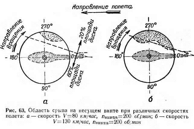
The graph shows that the angle of attack of the end profile of the rotor at an angle of about 270 ° approaching critical corners. This means that it is sufficient to allow a minor deviation from the specified flight mode (overstating the speed, insufficient number of revolutions), begins the failure of flow which will lead to the fact that on the whole part of the disc rotor hardly be created lift, but it will be an increased resistance to movement blade.
With the advent of failure on the helicopter rotor vibrates, worsen its stability and manageability. The degree of deterioration of the flight data of the helicopter depends on the size of the area covered by the breakdown. A small area of failure for example, while the failure on more than 20 ° / a drive screw can already be difficult correctable.
It shows a value area covered by disruption to the rotor diameter 12 m having a profile of the critical angle of attack 12 °, when 200 / min. When the flight speed in 80 km / h area of failure on the main rotor is still insignificant, about 8%. When increasing the speed of the 130 km / h area of failure has already spread almost 20% Smetana Square screw. It is urgently required to reduce the angle of attack, which might be done primarily in a decrease in the collective pitch of the rotor as well as a decrease in airspeed and rotor speed increases.
In order to prevent disruption expedient to the ends of the blades have profiles with high critical angle of attack.
Bad skin care propeller blades and its in-flight icing can dramatically reduce the critical angle of attack, which begins breakdown.
Thus, disruption of flow when the critical angle of attack at the retreating blade is the first factor limiting the helicopter flying at high speeds.
It should immediately mention that the increase in the number of revolutions of the rotor, as a measure to combat the disruption can be ineffective, as a result of the breakdown of flow can occur for other reasons, namely high-speed breakdown.
Stall speed for the profile of the rotor may occur at any angle of attack, throughout the operating range of angles in the case where the motion profile occurs with Mach number greater than M critical.
A critical number of the world calls a number M, in which in some parts of the profile appear supersonic flow area and, as a consequence, the wave resistance.
If the velocity of the profile of the screw in the air is much less than the speed of sound (L1 small number), then the flow smoothly streamlined profile, and the air in these conditions can be regarded as essentially incompressible medium, t. E. Does not change its density and temperature when the pressure changes.
It appears that in some circumstances to the compressibility of air must be considered, in some cases, the property of compressibility can be neglected.
The velocity of the profile is equal to or less than the velocity of sound 30%, the compressibility of the air can be ignored altogether, since in this case the aerodynamic profile of the coefficients do not depend on the speed of flight, and depend only on the angle of attack.
It is seen that even on the upper surface of the airfoil where the velocity of flow compared with the airspeed increases substantially, the flow remains smooth.
The influence on the characteristics of the speed profile also slightly at numbers of M to 0,3 0,7, although already observed manifestations n compressibility of air that coefficients.
When the number M reaches about 0,7, then the profile (usually the first on the top surface) appears the area where the speed is supersonic, and then suddenly, abruptly, goes into subsonic, which is accompanied by an increase in pressure of the air density. In such cases we say that the profile of "villages" shock wave.
With further increase of the speed jump on the upper profile gradually moves toward the trailing edge. Simultaneously with this, there is a jump and
the lower surface of the airfoil which also moves toward the trailing edge.

Education jumps accompanied by a significant disruption of flow, which naturally leads to a decrease in lift and an increase in the resistance profile.
Education disruption of flow speed on it is visible the profile of the boundary layer and shock wave. Shock wave reaches only up to the surface boundary layer. Here it is not distributed, as in the boundary layer velocity less than the velocity of sound, and the condition for the formation is the presence of the jump supersonic speed.
During the jump velocity decreases and the pressure increases, so the boundary layer flow of air particles takes place in the direction of the arrow. Accumulating, air particles as it break through the wall of the border streams, resulting in a breakdown.
The resistance profile, which appeared as a result of manifestation of the compressibility of air is called impedance. Most of the power loss of the rotor falls on the wave Poterna - impedance.
The resistance profile in failure in 13-14 times the resistance at a smooth flow profile. Changing lift and changing the position of the center of pressure causes a change in the moments generated profile. In some sections there is a tendency to nose down, while others - to pitch up, which dramatically negative impact on the stability and controllability of the helicopter.
The greater the total velocity flow profile, the greater the number M, and hence the greater the loss of the wave. This is clearly seen from the diagram of distribution power losses along the screw propeller blades shown.

The closer to the end of the blade profile, the greater the proportion of wave losses.
Thus, disruption of flow at critical velocity at the advancing blade is the second factor limiting the helicopter flying at high speeds.
Therefore, each helicopter has a flight speed limits and the numbers of turns of the screw (the engine), which are determined by wind tunnel and flight tests.
Maximum speed of horizontal flight helicopter reached when the need for flight capacity becomes available capacity.
If a helicopter mounted reciprocating engine, then its available capacity with increasing flight speed is not increased and remains approximately constant.
However, the required power with increasing flight speed varies as the resistance varies helicopter (fuselage and other parts).
Power demand is spent on overcoming the inductance, resistance profile and harmful.
First, with increasing velocity, the required power decreases as the creation of the same rod with increasing speed of flight requires less power. Power demand is reduced in proportion to the speed of flight. With further increase in speed resistance increases proportionally to the square of the velocity.
The speed at which the required power becomes available capacity is the maximum speed of horizontal flight. A further increase in speed is possible only by reducing the helicopter.
Last news:


Latest Video:


.
.
News
15.04.2024


